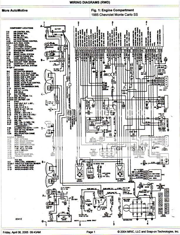
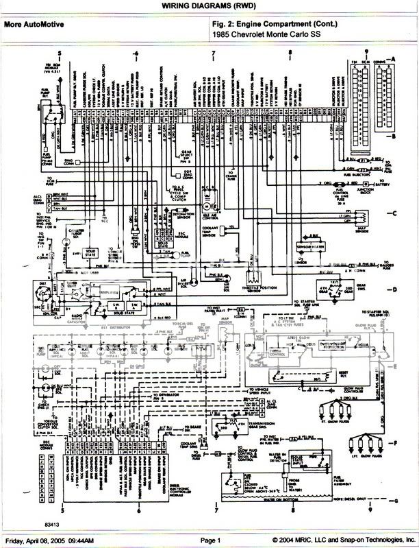
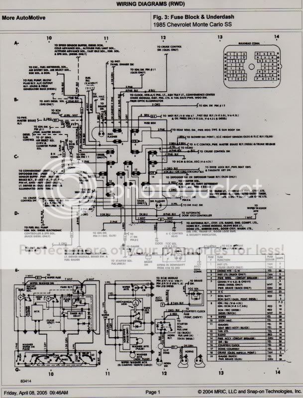
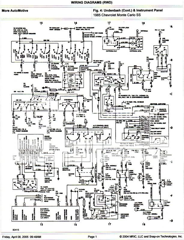
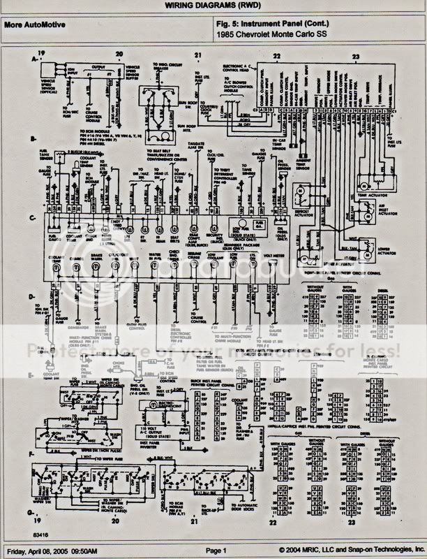
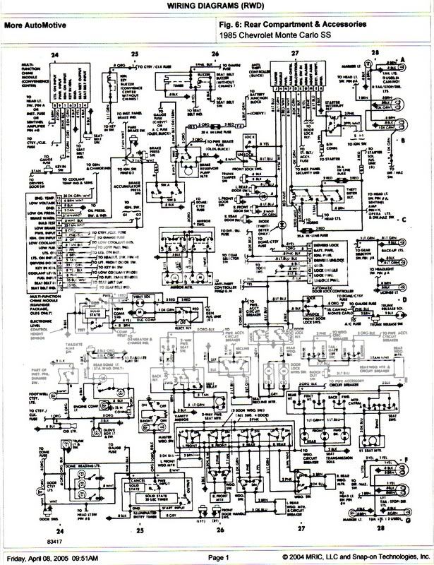
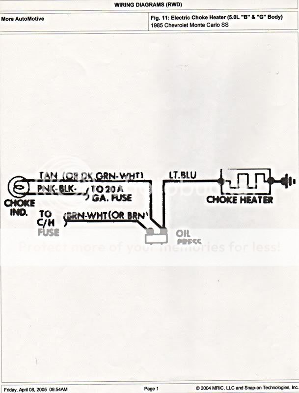
Members Login
Username 
 
Password 
    Remember Me  
Post Info TOPIC: Headlight wiring diagram needed.


Veteran Member

Status: Offline
Posts: 33
Date: Oct 8, 2009
Headlight wiring diagram needed.
Permalink Closed


Hi, can someone post a wiring diagram for the headlight circuit for an 83? I'm using a Hayne's book and I don't like the way it's printed. I want to check the low/high beam circuit. I've never used AllData but I understand it's good. Thanks.

__________________


Moderator

Status: Offline
Posts: 2150
Date: Oct 8, 2009
Permalink Closed


Upgrading Your Headlamp Wiring
DO YOU NEED TO DO THIS? Typically, if you keep your bulbs at 100W or lower, you will have little problem with meltdown of the OE wiring or controls as long as the wiring is in good shape and all connectors in the circuits are clean and free from corrosion. The only problem you might have is less than optimum voltage at the bulb. All automotive bulbs are rated at 13.5V, the output of the typical alternator. Any less than that and you start losing output from the bulb in a hurry. First you want to measure the output of your alternator, at the alternator. With the engine off, hook your VOM leads to the alternator securely. Start the engine and note the voltage. Shut off the engine and move the leads to the back of the bulb you want to check. Start the engine, turn on the lights and note the voltage at the bulb – you can do this for both high and low beam. If the difference between the output of the alternator and the voltage at the bulb is One Volt or more, you might consider upgrading your wiring as described here.

For reference, here are the pin connections for an H4 Bulb or Lamp. All are looking at the back of the bulb/lamp.


And shown below is the wiring you want to do if you are putting relays in the lighting circuits to handle higher wattage bulbs.


There are two options for putting in the relays – One, you can use the existing wiring and connectors in the car. If you intend on restoring the headlamps to original before you sell the car, this might not be a good option. If the OE wiring is suspect for any reason, this is also not a good option. Two, you can start from scratch with a couple of my relay kits, a couple rolls of 14AWG automotive wire, two lengths of 12AWG automotive wire; one in red and one in black, and two replacement H4 connectors from a good automotive parts store. The Napa/Echlin number is LS 6246 and the Calterm number is 08521. You build the harness from scratch and the only connections to the original wiring in the vehicle is the two control leads from pins 86 on the relays to the original Low and High beam circuits.


I’ve noted on the drawing where various sizes of wire should be used. If you run two separate wires from pins 87 to the two lamps on each relay, you can do that with 14AWG. As I’ve show in the drawing, I have you running 12AWG to a splice point and then 14AWG to each of the lamps. If you prefer to wire it that way, ensure you solder each splice and protect them with shrink tube or good electrical tape. If your application uses a H4666, H6545, H4668, or H4656, change the pin connections shown above as appropriate.


__________________
Pres. WICKED RIDES car club
www.wickedridesnj.com
www.wickedmontes.com


Veteran Member

Status: Offline
Posts: 33
Date: Oct 10, 2009
Permalink Closed

Thanks for the info

__________________


Moderator

Status: Offline
Posts: 2150
Date: Oct 10, 2009
Permalink Closed

np anything else you need?

__________________
Pres. WICKED RIDES car club
www.wickedridesnj.com
www.wickedmontes.com
Page 1 of 1  sorted by
 
Quick Reply

Please log in to post quick replies.


Create your own FREE Forum
Report Abuse
Powered by ActiveBoard